Mechatronics Autonomous Robot
A video of the robot winning competion (far side of field)
Checkoff attempt video (unsuccessful)
Challenge
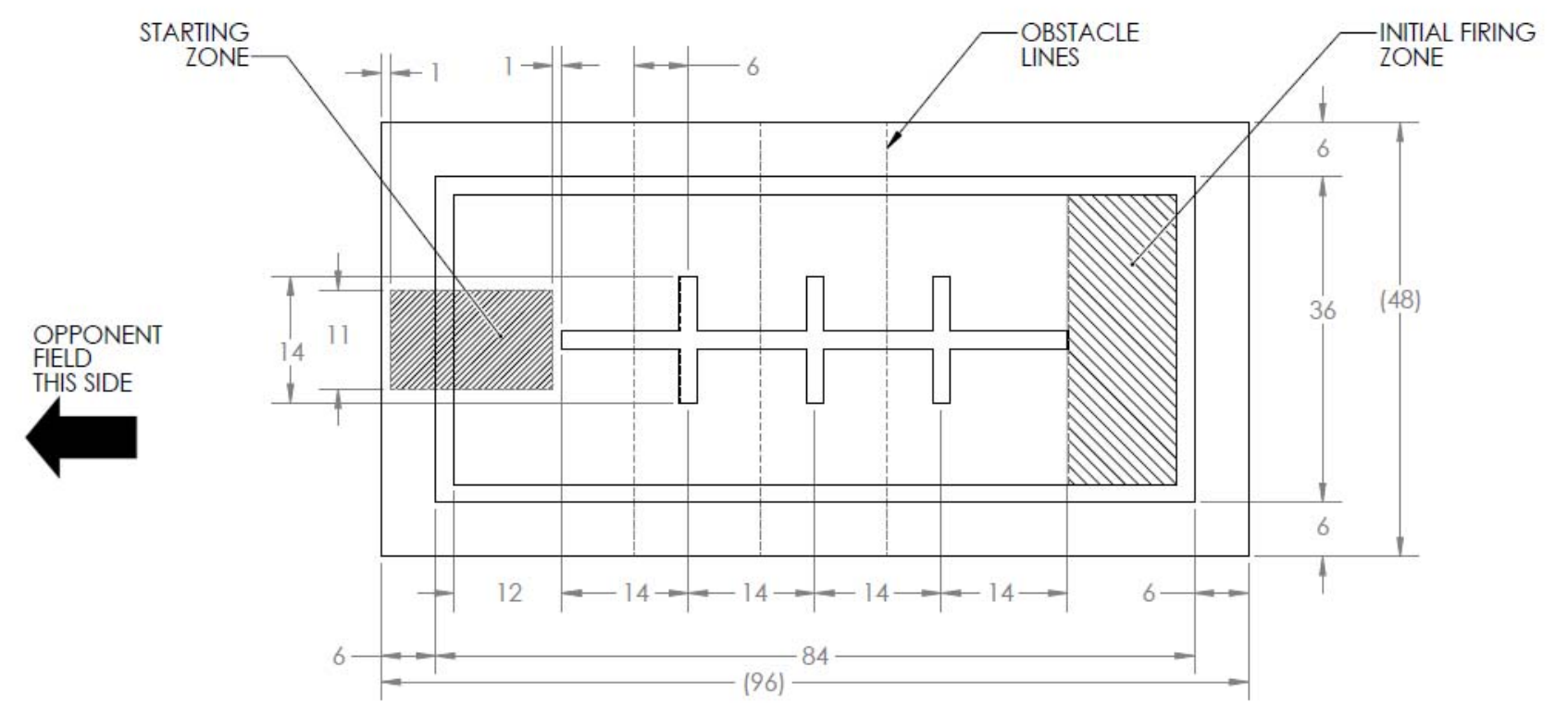
The robot had to start from one side of a 4ft by 8ft field and drive to the other side of the field into the Initial Firing Zone. There the robot would be allowed to shoot ping pong balls at its opponent who is on an identical, mirrored field. Lines of 2 inch wide tape about half a foot along the inside of the field to allow robots to follow the tape and get to the other side. Tape was also placed in the middle of the field in cross shapes, which also indicated where the obstacles could be located. A diagram of the field layout and an example double field can be seen below.

Obstacles
The path to the Initial Firing Zone can be blocked with obstacles in the form of wooden cacti that stood ten inches tall, ten inches wide, and three inches deep. These obstacles were fitted with beacons emmitting 1.5kHz and 2.5kHz frequencies designed to confuse our beacon detector focused on 2kHz frequencies. These obstacles were also fitted with track wires along the inside edges of the base of the obstacle to allow inductor circuits to detect their presence. There were three of these obstacles on the field that could be positioned on a line (not visible on the field) in front of the cross shapes of the center tape. These obstacles can be on the tape-following lines which made navigation of the robot more challenging. These obstacles were spaced apart from each other in such a way that a robot that was maxed out in volume could still (barely) fit in between the obstacles.
Design Overview
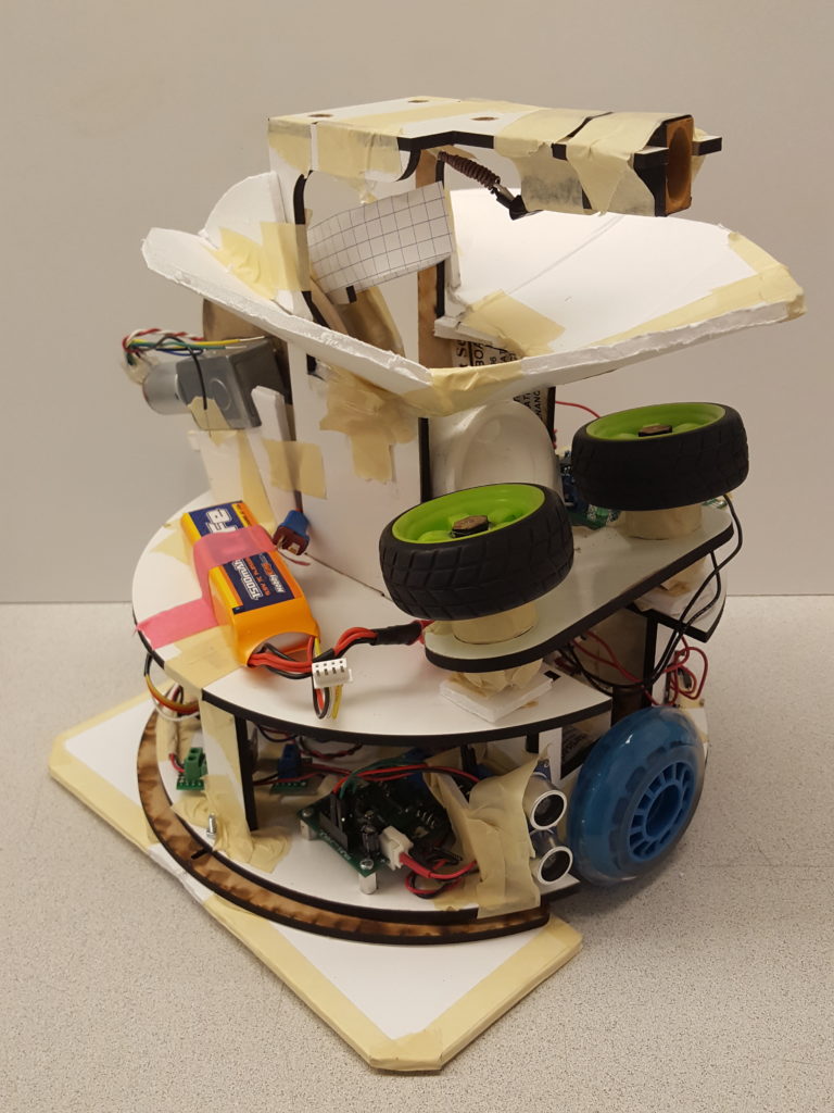
The robot consists of a circular design and two planes for the electronics and the launcher to sit inside. There is a tower in the center of the robot extending to eleven inches above the surface. Much of these design choices were made to fit in The Cube of Compliance, which was an 11x11x11 inch cube.
The circular base is 10 inches in diameter, which allows the robot to easily be within The Cube of Compliance, and will make sure the robot doesn’t hit anything while turning corners. If we had a square base, the corners of the bot may collide with the obstacles during a turn. The underside of the robot has the tape sensors, bump sensors, and two skids made out of half of a ping pong ball.
The first floor of the robot holds most of the electronics that do the sensing and control for the bot. The UNO Stack, H-bridge, and driver boards for the sensors sit inside the robot, and two motors are on the sides of the robot for driving.
On the second floor, there is the ping pong ball launcher, which has a custom mount for holding the pitching motors and being attached to the PVC T-fitting. There is a tower in the middle of the robot that holds the beacon, and two prongs that hold the beacon detector cone.

Beacon Detection
As the beacon on the enemy robot was the only reference point we were guaranteed to have at the start as well as the only way to find the enemy robot it was imperative that our robot be able to find it reliably and efficiently. As such the circuit shown below was adapted from the design created by Zee Moffatt and Barron Wong.
The circuit is a little different from the filters used by many of the other teams in that it consists of two pairs of filters and op-amp based comparators. As it was originally created following the transresistive stage a noise filter stage centered at 2KHz with a passband of 100Hz helps to remove the noise from lights, lab equipment and other interference. It also mildly attunes the 1.5KHz and 2.5KHz signals but not to the degree required for the filter. Next, a Schmidt Trigger is used to rail the received signal with hysteresis bounds set to avoid any noise that got through the filter stage. The ‘digital’ signal is then sent into the main filter stage which attunes the 1.5KHz and 2.5KHz signals by greater then 20dB. Next, a peak detector with a large RC time constant is used to improve the signal for processing in the second Schmidt Trigger that follows. This comparator creates the final signal seen by the microcontroller after it is run through a buffer to stop any effects of loading on the circuit. An LED provides a visual for the circuit’s functionality.
![]()
It is designed to be taller then it is wide in order to allow for a certain amount of error in the vertical placement while making sure that the detector would only see the beacon when pointed directly at it. On the back a slot the exact size and shape of the phototransistor holds it perfectly centered in order to make sure it doesn’t slip while the robot moves, something that happened with the paper beacon.
During testing we discovered quickly that light leaks were a major issue and that even the plastic was not thick enough to stop them. In order to maximize performance the entire shield was wrapped in black electrical tape to make it totally opaque as seen below. One more leak was found in that light was able to make its way up between the wires attached to the phototransistor. Once these were heavily sealed in tape we were able to have the beacon right above the shield without the detector being able to see it. The vertical design allowed us to have an almost 20 degree error in our vertical direction while limiting our horizontal detection to within 5degrees, allowing for very accurate aiming.
![]()
Tape Sensors
Another integral part of the robot was the tape sensors, which allowed us to see what was below the bot on the field. The interesting thing about this circuit is that each sensor actually has two completely separate components; one for the LED and one for the sensor.
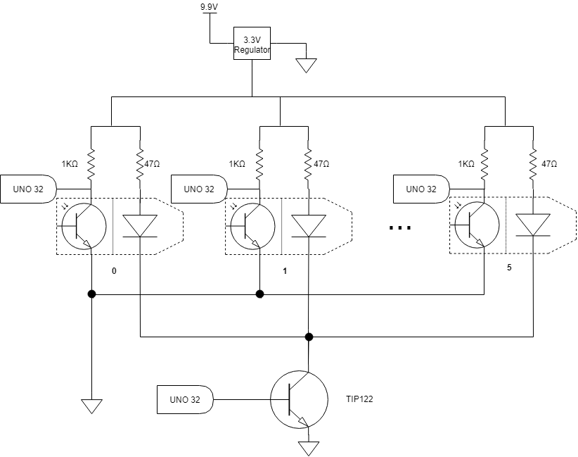
In the final design, as seen below, each LED is in series with a 47 ohm current limiting resistor on their cathode side. The anode side of all six tape sensor LEDs are tied together and attached to the collector of the TIP122, putting it into a sinking configuration. With the TIP122’s emitter grounded the microcontroller is able to turn the LEDs on and off by setting a digital pin high or low. For testing purposes a switch in series with a series 220 ohm resistor to mimic the microcontroller’s internal impedance was hooked up to the transistor. The TIP122 allows the LEDs to source the current they need to function while still being controllable from the microcontroller for the purpose of synchronous sampling.
For the internal phototransistor the emitter was tied to ground while the collector was in series with a 1K ohm resistor. By connecting an microcontroller ADC pin between the resistor and the transistor it is possible to measure the voltage drop across the phototransistor, which is proportional to the amount of reflected light it is seeing. The reason a 1K ohm resistor is being used here is that it tunes the gain to be optimal for the distance beneath our robot. While the on tape, off tape voltages are not quite digital, they are several volts different which is more then enough for easy differentiation in software.
The actual circuit construction was split into two pieces as seen below. One board acted as the power board; containing the regulator, protection diode and the TIP122 transistor. It is a fairly small board with three inputs; power, ground and an LED on/off signal. It also has three outputs; ground, LED power and transistor power. The second board was the I/O board for the sensors. In the image the right side of the board contains the two connectors used by the LEDs. The right side contains the connectors for the transistors. The color coded wires coming out of the board head back to the microcontroller.
Track Wire Sensor
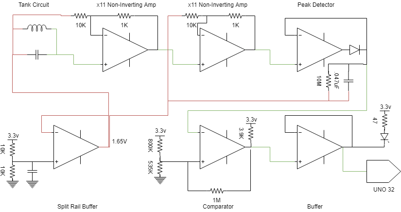
Another unused circuit was the track wire sensor. When originally planning our solution to the task at hand we assumed that we would have to be able to get back to the front and as such the track wire sensor would be helpful in identifying when to hide behind an obstacle.
Based off of the circuit from lab 1, the circuit below shows the track wire that we designed for this project. This circuit is far more compact then the original circuit it was based off of, allowing it to use only two chips, saving a lot of space. It starts off with a tank circuit tuned to around 27KHz. The output of the tank circuit passes through two gain stages for a total of a little over 100 times gain. The new, larger signal then passes through a peak detector with a very large RC constant in order to keep it within the comparator bounds at all times. The comparator itself is actually an op-amp based comparator in order to minimize the number of chips needed. It’s bounds were tuned by looking at the output of the peak detector at various distances from the track wire. The output of the comparator was passed into a buffer to stop any loading effects from the UNO and an indicator LED was added.
Launcher
The ball launcher was designed remembering that it has to shoot the ping pong ball roughly sixteen feet if both our robot and the opponent robot is on their respective sides of the Initial Firing Zone. Many teams had chosen to use the counter-rotating wheels, but we were skeptical of the current draw of having two motors spinning continuously and potentially blowing fuses on the Uno Stack. We would also need a third motor to get balls into the counter-rotating wheels. Initially tried to use a spring-loaded mechanism to fire the ball as seen below. After prototyping the design and testing it, the ball could only go about 6 feet, and each shot was not very accurate.
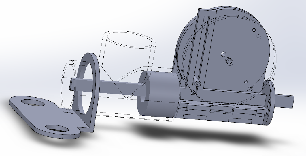
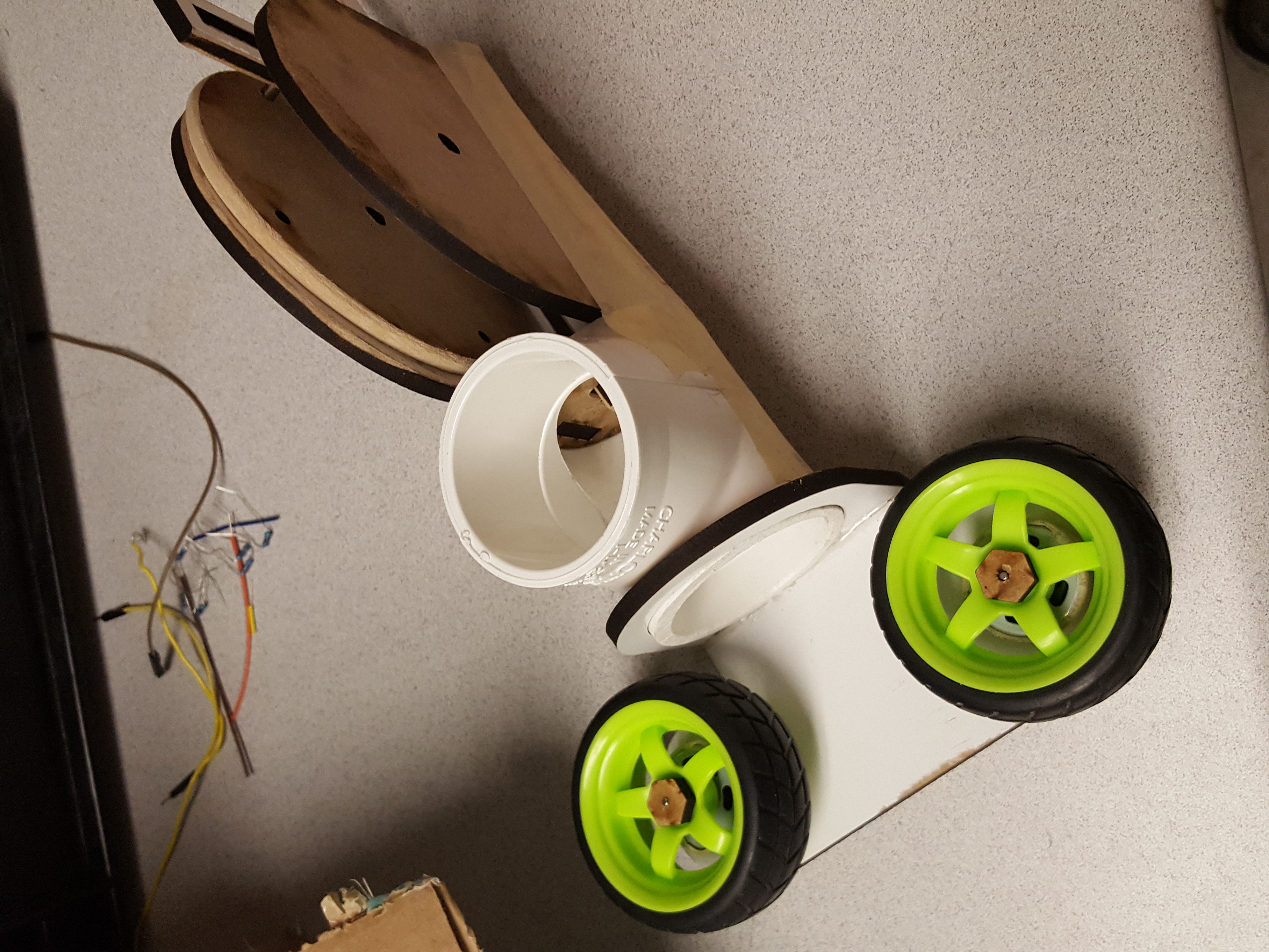
After seeing that many teams were using counter-rotating wheels with little to no trouble, we switched to that mechanism. After some time on SolidWorks and some laser-cut parts out of MDF, we created a simple mount for the motors and redesigned part of the failed spring-loaded prototype to act as the ball plunger to push the balls into the wheels. There is a slider piece that act as the plunger, and a long hole vertical with a pin allows the mechanism to turn rotation motion in to linear oscillation. When the plunger is pulled back, the next ball loads from gravity, and then the plunger pushes the ball in between the pitching motors to make it launch. The benefit of this design is that the motors can just continuously run in a single direction, which means a pin can just have a PWM signal in software. This worked tremendously well, and even at a duty cycle of 10-20%, we were easily getting the range we needed. The three motors were controlled using the DS3658 Driver board.
State Machines
When we first started the project, we designed a large, multilevel state machine that assumed we wanted to go back to the IFZ. When we actually started writing code though, we went with the incremental design approach, which caused our initial design to be a single flat state machine. We did this by first writing the state machine for tape following. Once we got that working, we added corner counting to the state machine so that we could detect the IFZ (two corners indicates we are in the IFZ). Next, we added functionality to detect the beacon from the IFZ and turn on the pitching motors to start shooting. Finally, we added functionality to align the bot by using the beacon at the very beginning of the round. After designing most of the functionality for the challenge in a single flat state machine, we decided that it would be best to refactor the code a bit in order to make it more modular, and easier to read. Therefore, we took our state machine and split it up into one top level state machine and three sub state machines.
The diagram below shows our FindIFZ state machine, our largest and most complex state machine. The main function of this state machine is to follow tape, and count corners until we get to the IFZ. It is also able to resolve collisions. The state that we start in, and always go back to, is GoForward. This state simply drives in a straight line with the middle front and rear sensors on the tape. If the front bumper is pressed down, then the bot will enter the SmallBackup state, and the proceed to cross the field. The bot uses a variable to keep track of which side of the field it is on, and turns left or right, accordingly. Then the bot enters the DriveForwardBlindly state (named because we ignore tape sensors while crossing the field so that we don’t get confused by the center tape). If all goes well, the bot will drive forward for five seconds, and then start looking for the tape on the other side of the field and realign with it. However, if the bot hits an obstacle while crossing the field, it will pause the field crossing timer, and do a small back up away from the obstacle it hit, and then resume the field crossing timer and go back into the DriveForwardBlindly state. After we’re done crossing the field, we’ve successfully resolved the collision and can go back to our GoForward state and resume tape following.
Final Design
fter assembling the robot together and testing each individual part along the way, we were ready to test the entire unit at once. Most of the major testing went into making sure the state machine behaved perfectly, adjusting the speed of the launcher’s pitching motors, and checking that the sensors were triggering events.
For official Check-Off, our robot navigated through three courses created by a random field generator. Our robot successfully completed the two out of three fields to satisfy the check-off requirements. The robot was able to drive across the field from the Starting Zone to the Initial Firing Zone while avoiding obstacles, and shoot ping pong balls at the body of the stationary opponent twice.
A video of one of the attempts at a checkoff can be found here: https://www.youtube.com/watch?v=wNWk9Dwdb6A
Another (more successful) checkoff attempt can be found here: https://www.youtube.com/watch?v=zfO1PEZOL9g
Finally, this video shows the bot during the final competition, in which we faced off against the Cowbot, and hit their tin can: https://www.youtube.com/watch?v=Uoz3Ah66wBg
On Friday, December 7th, there was a competition against other robots in the class in the form of a tournament. While this competition was purely for fun, there was another layer of difficulty including aiming at an opponent that can move. Before the competition, we made some adjustments, such as increasing the speed of the pitching motors so that the ball would travel farther as we expected our opponents to be in their respective Initial Firing Zone about 16 feet away. We thought about resetting the robot so that it would find the beacon to aim and shoot again, but we did not have the time to implement it. Another challenge also came from the environment of the room. All of our testing was done in Jack Baskin’s Fabrication Lab, which is a small fabrication lab with lights but no windows for sunlight. The competition’s environment was the largest lecture hall at UCSC with a big stage in the front and plenty of lights all around the room, possibly confusing our tape sensors of what is light and dark. The audience may also have cameras with infrared lights, which could confuse our beacon detector.
We faced a few opponents whose bots varied in their own performance and robustness. In those rounds, we either shot the body of the opponent twice, shot the tin can, or the opponent did not perform well enough to continue the round. We were very surprised to find out that we won the competition, so we would say the performance of our robot was pretty phenomenal.

Struggles and Challanges
While creating this robot, we encountered some challenges that we didn’t expect. One of the challenges was getting parts we needed, including finding motors and electronics of good specification. Some other groups in the class were offering to give parts because they bought them in bulk (which can be cheaper), so we joined in and bought motors, wheels, and MDF from other groups to make acquiring parts easier. We ended out accidentally breaking our drive motors, so we couldn’t fully assemble our robot until the third week because that’s when the replacement drive motors came in. This extra time did prove to be useful though, since we continued to test and integrate our sensors, making sure they were very robust.
Another challenge we faced came in the form of mistakes. Zach C. accidentally shorted the power distribution board by inserting the USB cable in a place that connected power and ground on the battery. Despite this, replacement power distribution boards were given and extra care was taken to make sure it doesn’t happen again. This did not set us back in the project, but it did prevent us from attempting the professor’s early beer checkoff opportunity.
The biggest challenge for all of us was the amount of time we had to dedicate to this project and finding times to meet up. The three of us have other classes outside of CMPE118/L and CMPE218/L Introduction to Mechatronics, such as engineering projects and work. We faced this challenge by doing what we knew we could do to make our time as useful as possible, such as working on the state machine when we were waiting on motors to arrive, or breadboarding, soldering, and interfacing the tape sensors with software without knowing the layout of the tape sensors beforehand. We made sure to always have some part of the project in the works to make sure we had it ready when we needed it as well as save time in the end for debugging and testing.
